A BVM with a shaking or jittering picture is usually repaired by a targeted recap of the D & E boards as shown in my video below:
Category: Retro Gaming
Commodore 1084 SCART Mod
Most revisions of the Commodore 1084 were produced with the same internal circuitboard for all regions – which for a monitor with factory RGB inputs means two important things:
- All regional versions are compatible with both NTSC and PAL signals due to reuse of parts.
- The North American version has an unused hidden SCART header for RGB input! Just add a connector 🙂
I truly didn’t expect for the process to be as simple as adding a SCART header to the board, but turns out it is! Here is a video showcasing the process from start to finish:
The right-angle SCART header is actually very hard to find as it’s been discontinued in all major parts suppliers. However there is a lot of NOS in Hong Kong that you can get off of eBay. That’s where I found mine – only downside is the 3 week delivery time.
Sony PVM 5041Q No Composite Fix
This week I fixed a 5041Q which had a broken composite input. You can see a summary of the repairs on my YouTube Channel:
The REMOTE input on the back of the monitor was shorting out the Line/RGB switching circuit, sending 12v at all times regardless of if the switch was toggled on or off for the front of the monitor. Simply removing the port, checking for broken pins, and reseating the REMOTE plug resolved the issue.
NEC DM-2000P CRT Monitor
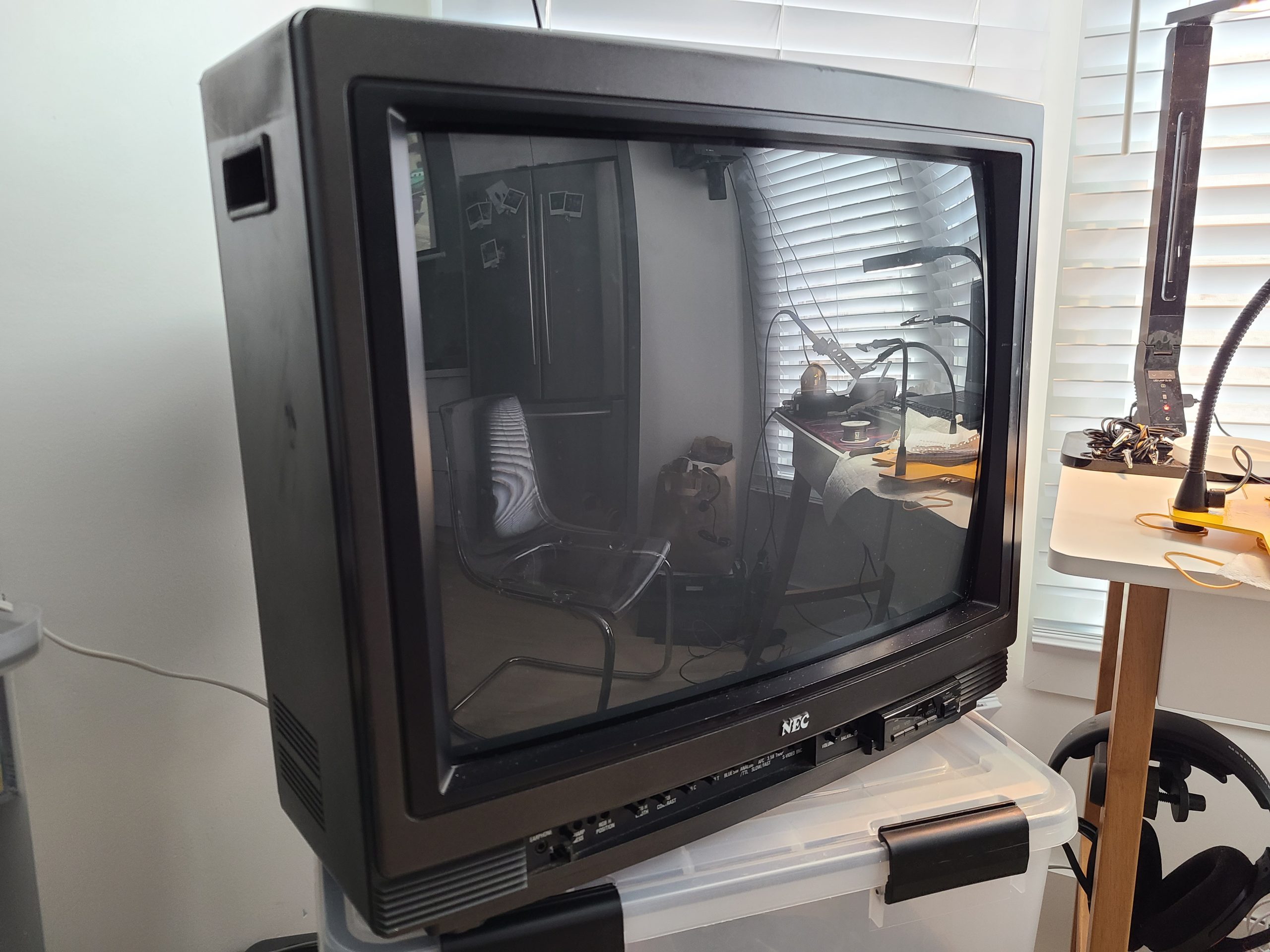
I recently got my hands on a NEC DM-2000P CRT Monitor that needed geometry and color calibrations. I noticed that there is pretty much zero documentation on this monitor online – I guess none of it got digitized. Last mention of it I saw on the internet was from someone who apparently had a hard-copy of the user manual in 2010…
I am going to document as much information here as I can so that anyone else who has this monitor or is considering buying it (or a similar one: DM-2000A, DM-2600P, DM-3000P) can be more informed.
Specifications
I haven’t even been able to find a spec sheet on this monitor so here is what I’ve been able to determine:
- Screen Size: 20″
- TVL: 450?
- Tube: NEC E814B22
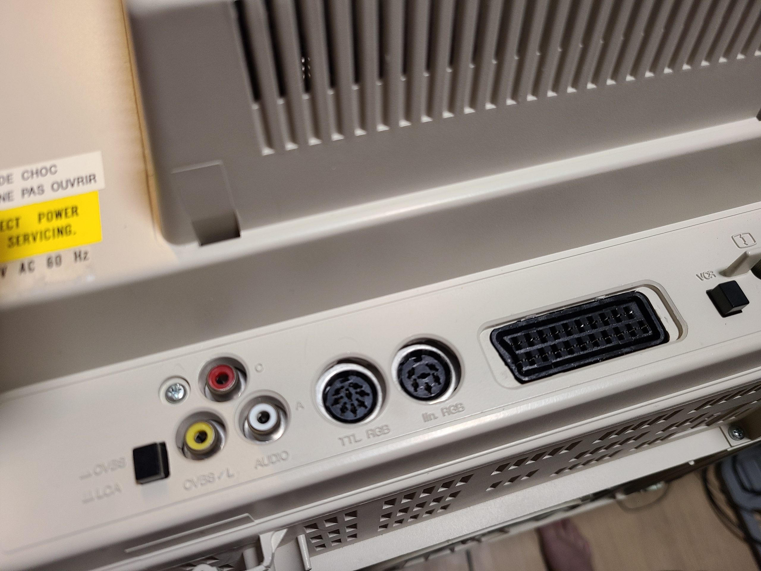
- Inputs: 34-pin RGB, 1x VTR, 1x S-Video, 2x Composite, 1x external remote
- Multisync 15-35.5Khz horizontal, 50-87KHz vertical (Source)
- RGB Capability: Analog & TTL
- Year of manufacture: 1989 (datestamped inside)
CRT Gallery (assembled)
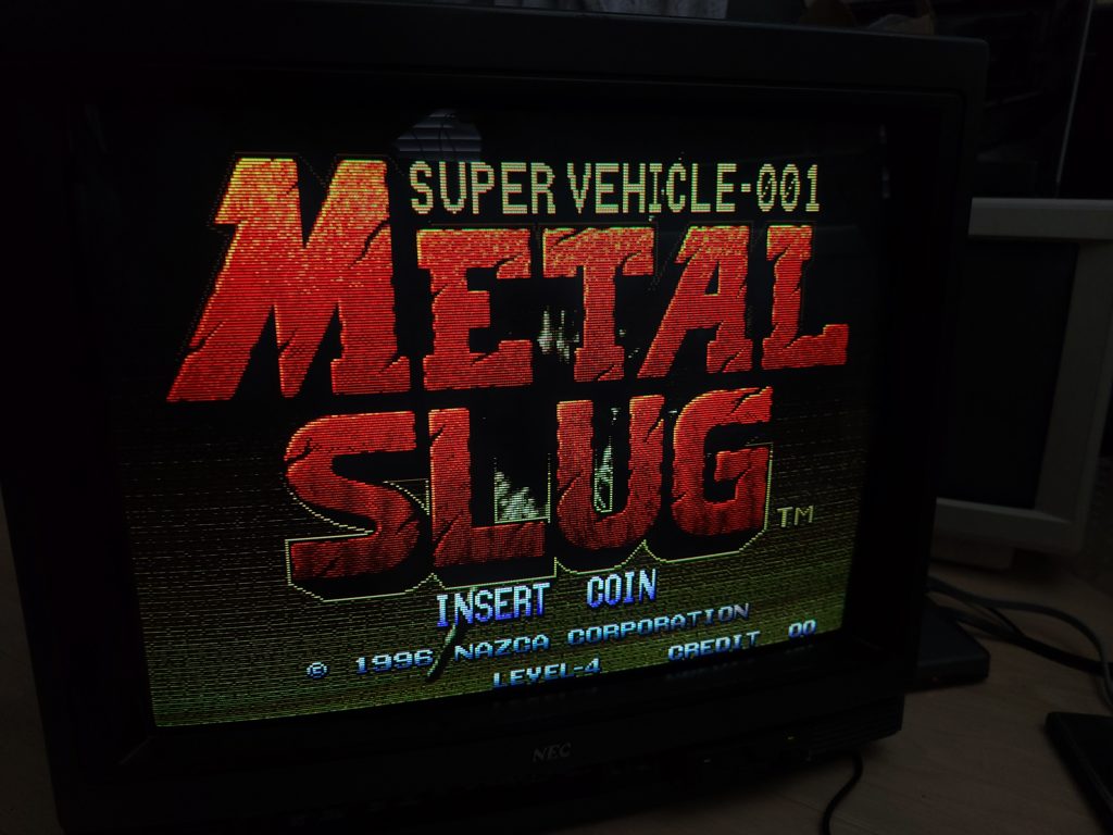
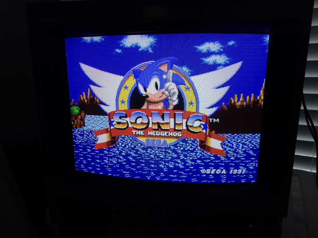
Metal Slug over RGB 
Metal Slug over RGB 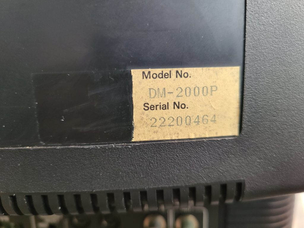
Serial # 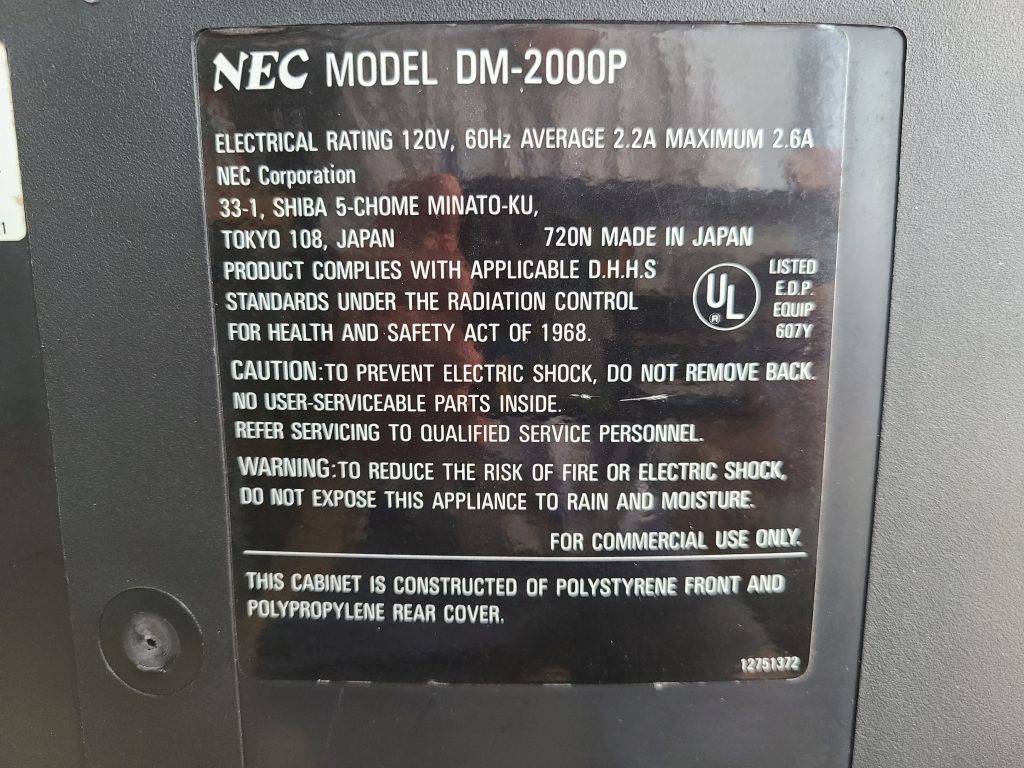
Model # 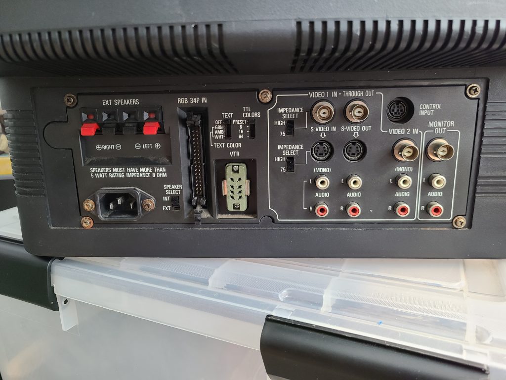
Rear Inputs 
Input Selection 
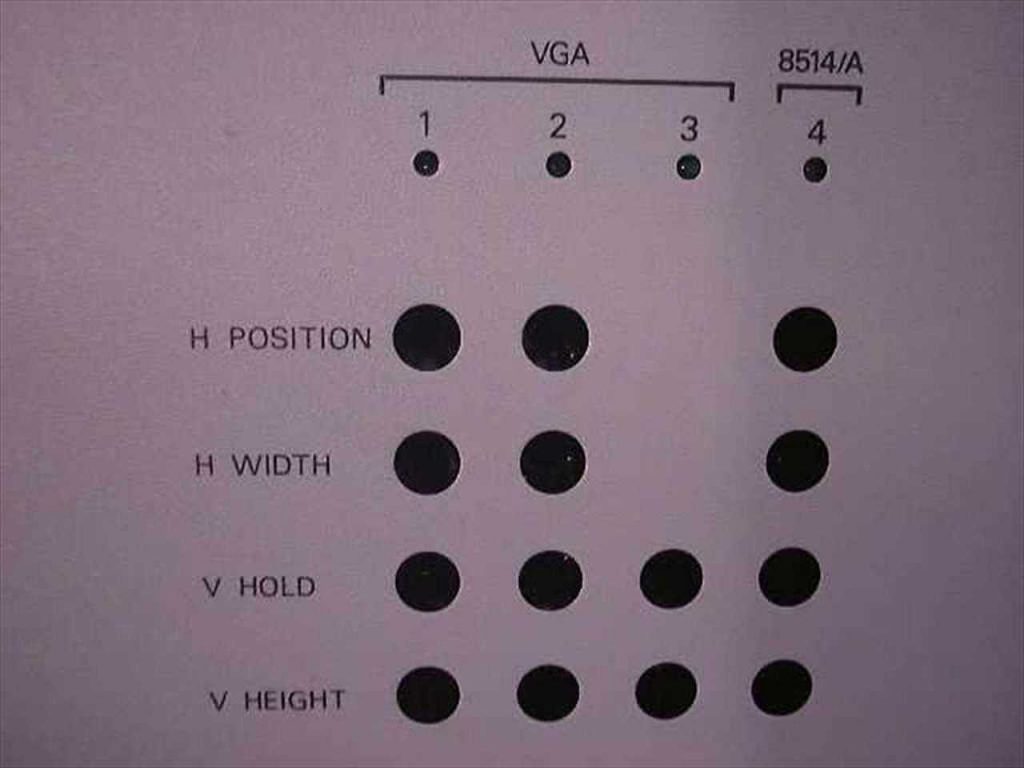
Front Panel Controls / Adjustments 
Front of NEC DM-2000P
Publications / Press
I found a blurb in an old scan of PC Magazine (May 14th, 1991, page 374-375) about the 30″ version of this monitor – the DM-3000P. It’s identical to this monitor except for the larger picture tube size. Here is my transcription of the article from the image I found.
NEC is certainly one of the big names in computer monitors, and here is a big monitor bearing the NEC label. Unfortunately, besides the logo, the DM-3000P shows little evidence of the usual NEC quality. The monitor has a 30-inch diagonal screen and a load of features, and its price tag is not small. At $5,600 ($10,734.08 – adjusted for inflation), the DM-3000P isn’t nearly the lowest-priced monitor in this roundup, and it sports moderate features to boot.
With the DM-3000P, you get a unit with specifications comparable to those found in some of the competing models. For example, the 50-87 Hz vertical and the 15 to 35 kHz horizontal scanning frequency ranges are on a par with the others. The DM-3000P’s 0.80 mm dot pitch is large when compared with smaller monitors but still a bit better than average for this class of display.
The unit comes with internal stereo speakers (though these sounded tinny at best), external speaker connections, and stereo signal-out connectors for an amplifier. The unit supports both composite and S-video signals, and it can pass these signals through to other monitors.
While it is possible to connect directly with the monitor, you will want to use the IPS-100 VGA interface that is included with the unit (see below for pictures). This interface is a separate video controller box that modifies a VGA or 8514/A signal to give you better images on-screen. The monitor itself only provides one set of analog controls for basic picture geometry settings, but the IPS-100 interface adds additional controls that allow you to adjust for optimal image size as you move between different display-adapter modes.
In an apparent contradiction, NEC specifications claim the ability to handle the signals up to 1024-by-768 interlaced, but they only claim a monitor resolution of 640-by-480–which means that you can feed the higher resolution signals into the controller, but the monitor won’t be able to resolve a crisp image for anything finer than 640 by 480. In addition, the DM-3000P has a bandwidth of only 20MHz, which is lower than competing designs and limits its ability to produce clear high-resolution images.
Performance results were erratic. The image was sharp and well-converged at the center of the screen, but the beams spread a bit and lines got thicker toward the corners. There were also significant horizontal convergence and pincushioning problems with this model, especially in the lower right corner.
Overall, the DM-3000{ is a less than attractive value. Larger than some of the units in this review, the DM-3000P comes with adequate image quality and a barely sufficient collection of features. If you are looking for a large-size video and VGA display, you could easily find a better buy than the DM-3000P.
— Alfred Poor – contributing editor of PC Magazine.
PC Magazine, May 14th 1991
NEC / Sony 34-pin RGB Info
The 34-pin RGB input is the same pinout as Sony’s standard input, which is well documented online. You can use a floppy drive cable as the connector for the TV-side of your adapter if you choose to make one yourself like I did:
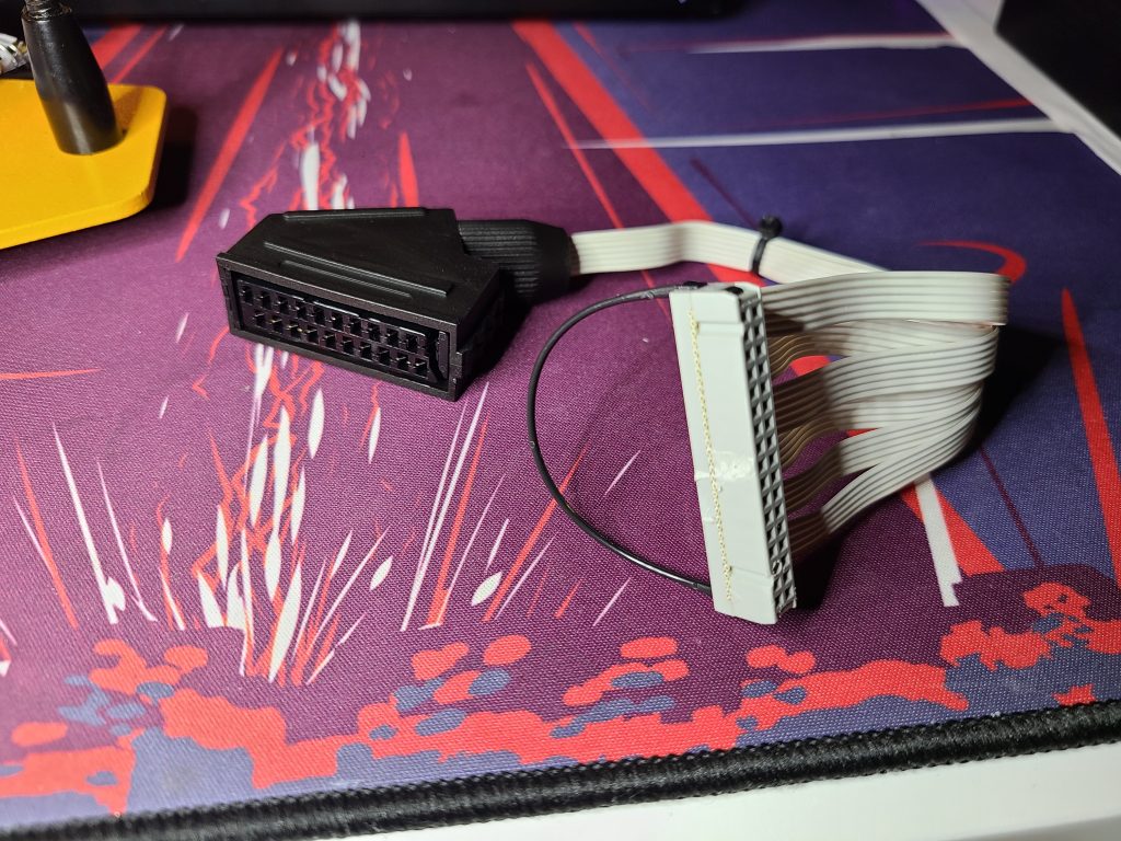
If you do use a floppy cable, take care to test the pins yourself using a multimeter to understand how the wires translate to the pins on the connector. The pin configuration of floppy cables is typically a side-by-side row pair, whereas the pin configuration of the NEC/Sony connector is two columns.
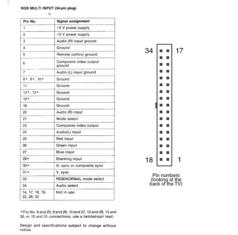
You only need to wire up the following pins shown below. The floppy wire you use will be different from cable to cable so I won’t bother trying to explain that part. Just make sure that whatever wire you use is leading to the correct pin on the TV’s connector or nothing will work. CSYNC is assumed at the source, I have not tested with sync over composite video.
Note that CSYNC is fed to both the H and V sync pins even though the diagram above says H-Sync supports composite sync… I couldn’t get vertical lock on my picture without hooking up to both H and V Sync pins.
| NEC Pin # | SCART Pin # | |
| Ground | 6 (or any other ground) | 4, 5, 9, 13, 18 |
| Red | 25 | 7 |
| Green | 26 | 11 |
| Blue | 27 | 15 |
| Sync | 30, 31 | 20 |
| Audio L | 24 | 6 |
| Audio R | 20 | 2 |
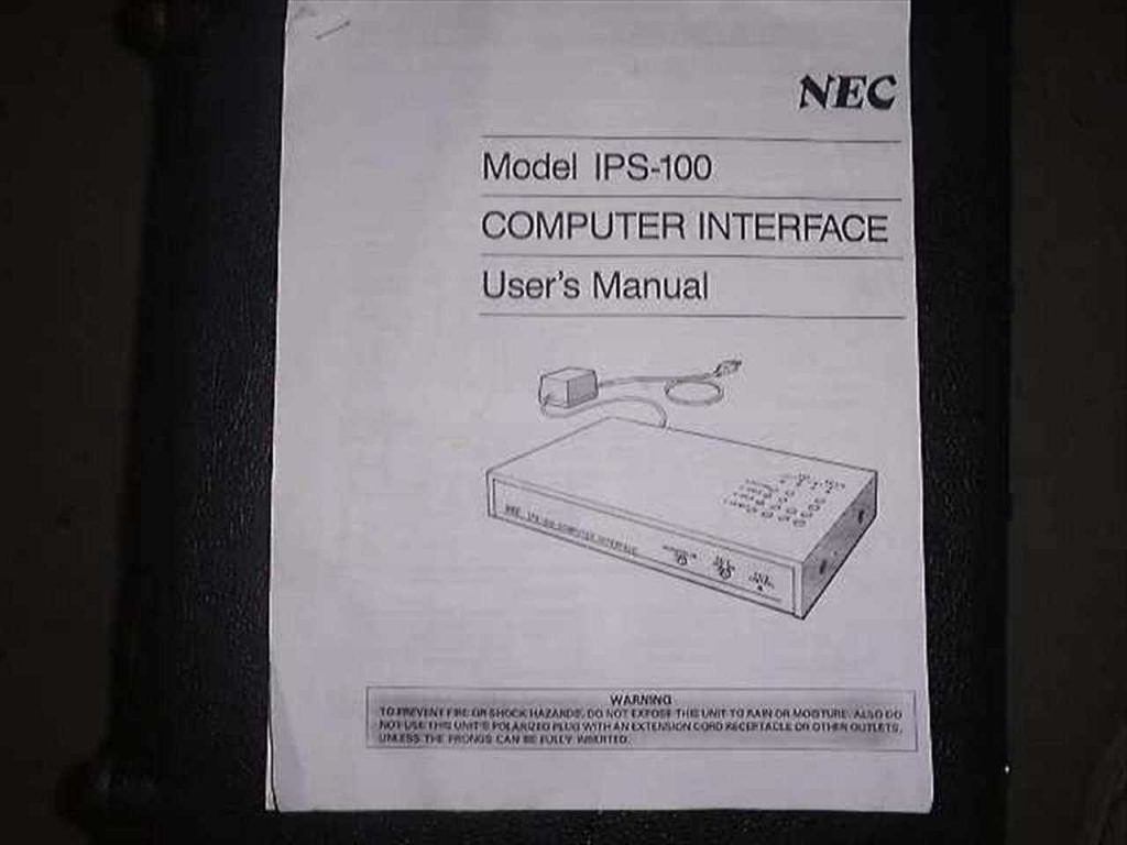
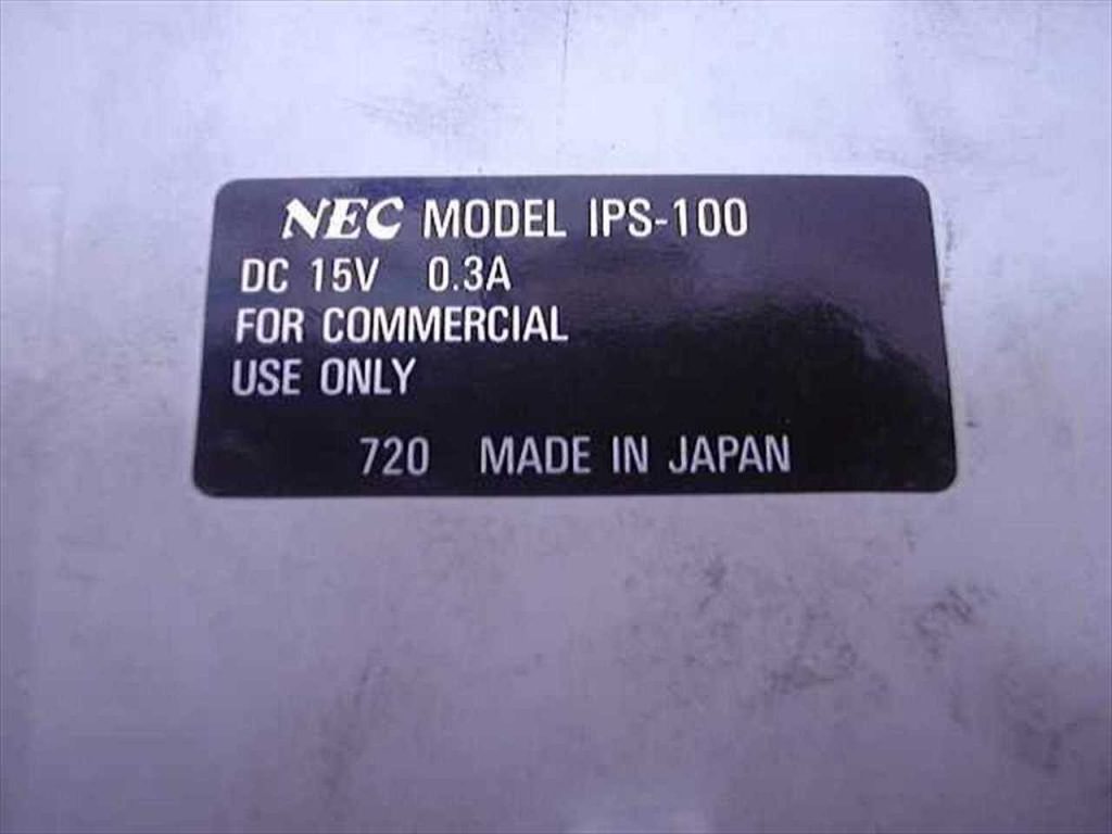
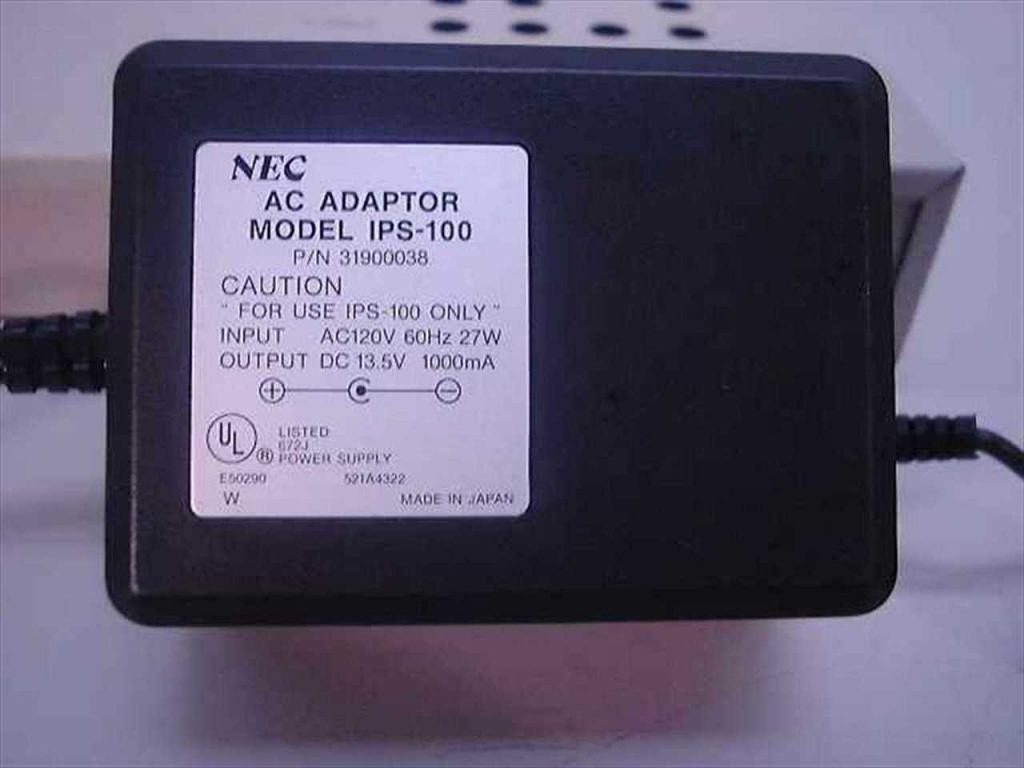
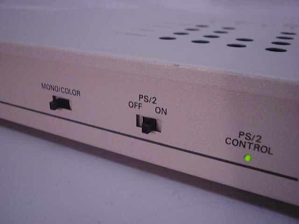
NEC IPS-100 interface
This item was mentioned in the PC Magazine article I mentioned earlier – it appears to be a conversion box to downscale high resolution VGA to 640-by-480 as well as provide compatibility with different common video input connectors. I found a listing on recycledgoods.com for one that was already sold, I downloaded the pictures in case they eventually get lost:


Disassembly
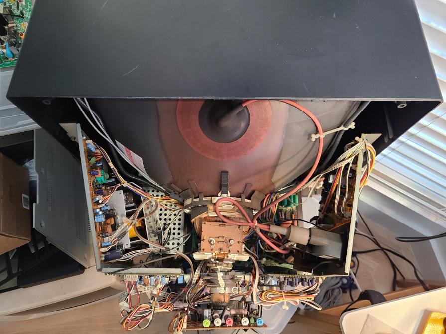
Overhead 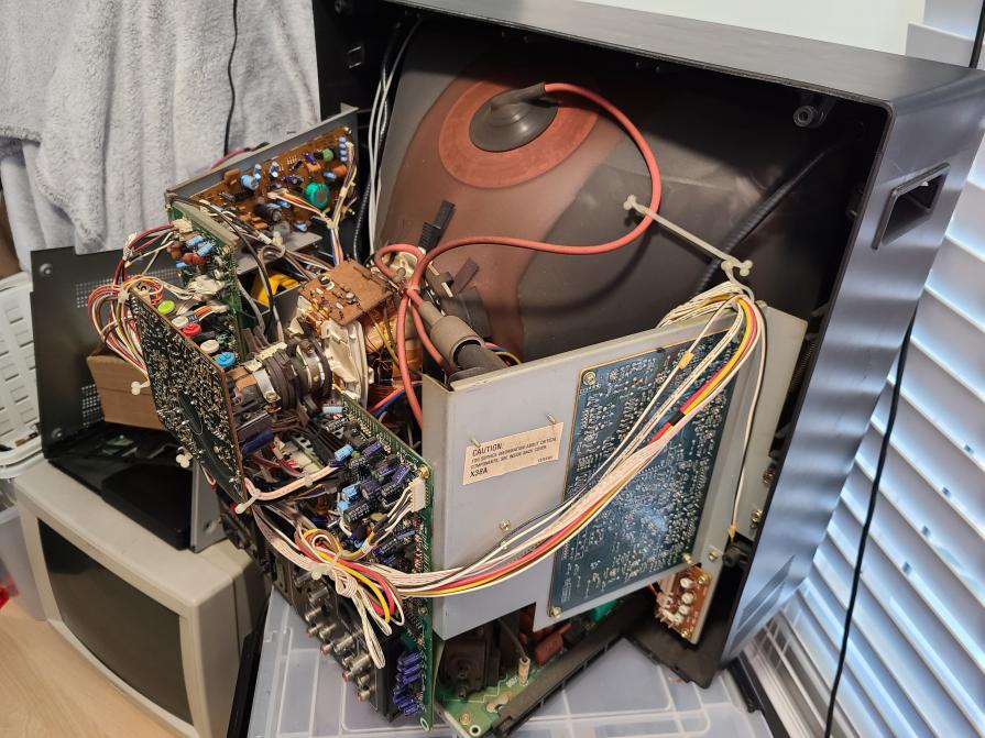
Left side from rear 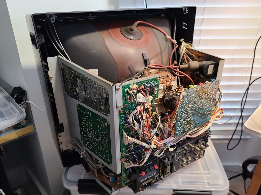
Right side from rear 
RGB Drive/Bias 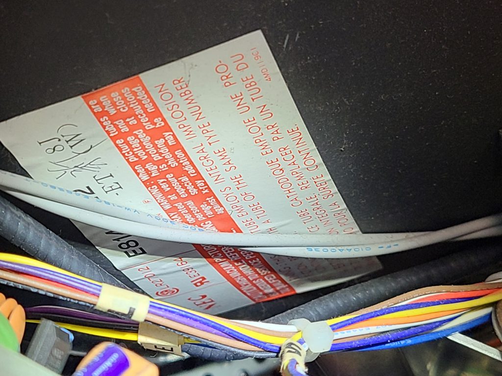
Tube Label 
Pots and oscilloscope tester spots
None of the potentiometers inside are labeled except those you can see in the “RGB Drive/Bias” image above. Those are R-Drive, R-Bias, G-Bias, B-Drive, and B-Bias. Nothing else is labeled. Notice there is also no adjustment for G-Drive.
RGB-Pi (OS 3) Screen Deformations & Sync Issues Fix
2023 Update: RGB-Pi OS 4 seems to have resolved all this nonsense once and for all. I suggest just updating to that OS and forgetting about trying to get OS 3 to display correctly if you’re having issues.
RGB-Pi is an excellent pixel-perfect emulation solution which gives proper 240p output via SCART to RGB-compatible CRT monitors.
Although compatibility is high out-of-the-box, many CRT monitors (especially professional/non-consumer models) will not accept the csync signal that RGB-Pi outputs. There are two different issues that can happen but both involve the same problem – you may have issues with only the RGB-Pi menus, only with emulation, or with both.
If your screen looks like any of the following pictures, this guide will most likely will fix your problem:
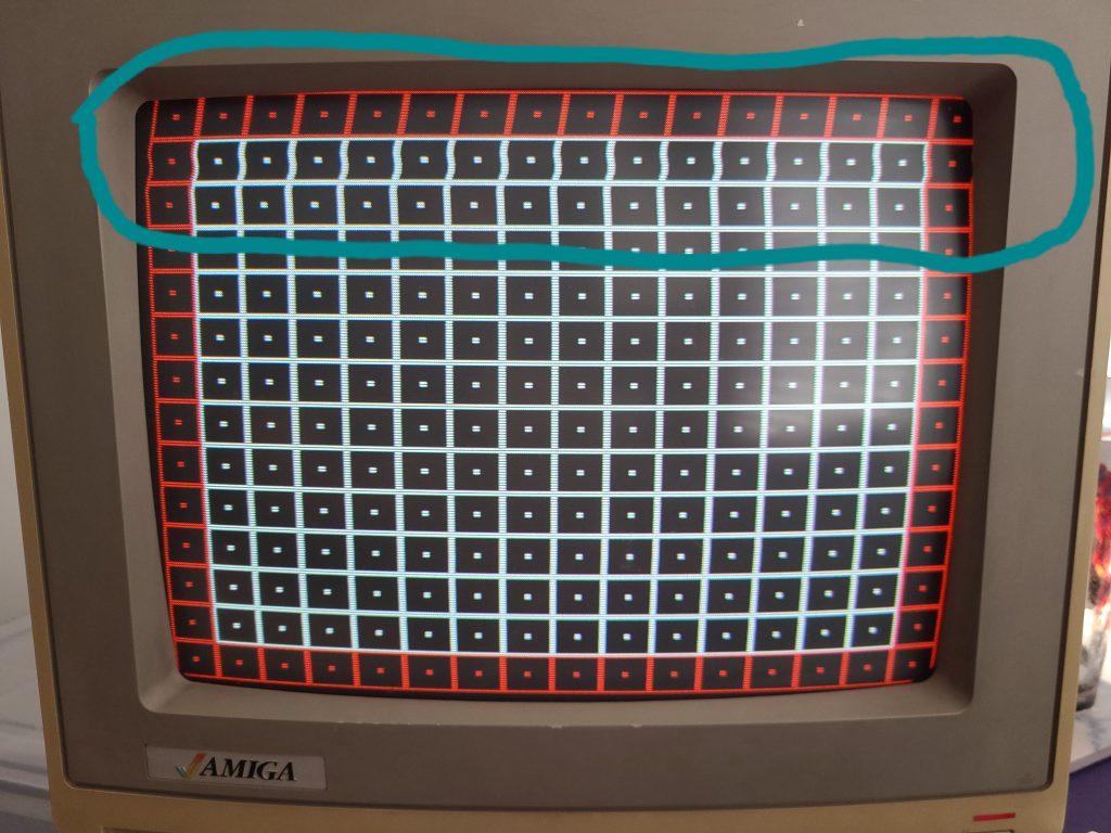

The RGB-Pi OS has two different “configurations” for displaying 240p content. The first displays the user interface (the menu of RGB-Pi where you select your game or change settings) and the second config is for displaying 240p emulation. Sometimes only one of these configs will have sync issues on your TV, sometimes both of them will.
OS/UI Sync Issues
If you have sync issues with the main menu of RGB-Pi OS, you need to read this section, otherwise skip it.
To fix sync issues happening on the main menu of RGB Pi (see 2nd image above), you will want to edit a file called config.txt. This can be accessed any of the following ways:
- Plugging in your RGB-Pi micro-sd card into a Windows or Linux-based computer
- Connecting to your Pi via SSH
- Connecting to your Pi via SCP/SFTP
In method #1, you will find it at the root of the sd card. In methods #2 and #3, you will need to browse to the /boot directory to find it.
Once you open the file with a text editor, you will see this on the first line:
hdmi_timings=320 1 10 30 40 240 1 3 4 6 0 0 0 60 0 6400000 1These are the settings used to generate the video signal of the RGB-Pi OS. If you are wondering what these numbers all represent, here is a handy chart in order of each setting’s appearance for hdmi_timings:
| h_active_pixels | h_sync_polarity | h_front_porch | h_sync_pulse | h_back_porch | v_active_lines | v_sync_polarity | v_front_porch | v_sync_pulse | v_back_porch | v_sync_offset_a | v_sync_offset_b | pixel_rep | frame_rate | interlaced | pixel_freq | aspect_ratio |
| 320 | 1 | 10 | 30 | 40 | 240 | 1 | 3 | 4 | 6 | 0 | 0 | 0 | 60 | 0 | 6400000 | 1 |
The only two numbers we care about here are h_sync_pulse (4th number in the list) and v_sync_pulse (9th number in the list). These are the numbers that control most of the sync deformations you encounter. Now that you know where to find these numbers, continue reading Adjusting the Sync Pulse below to learn how to adjust these numbers and fix your menu sync.
240p emu sync issues
If you have issues with sync during game emulation, you need to read this section, otherwise skip it.
Each console RGB-Pi is capable of emulating has its own configuration settings to produce the correct pixel-perfect 240p picture on a CRT monitor. Usually all that needs to be adjusted to fix a sync deformation is the V-Sync or H-Sync pulse value. These values can be found in the following file:
NOTE: This file is only accessible via SSH/SFTP!! You won’t find this file on the SD Card!
/home/RGB-Pi/data/timings/console-timings.txtIn this file you will see a line for every console, both 60Hz and 50Hz seperately. They are separated because 50Hz requires a different amount of horizontal lines to be displayed. You may have already discovered before reading this guide that playing your games at 50Hz fixes the sync issues – however that is not a desirable solution for most people. The actual solution will be to change the sync pulse lines for every console in this file. Fortunately they all use the same default values, so you don’t have to manually test each console for different numbers. Pick one console you can test a ROM with (I picked snes60 for 60Hz SNES emulation).
| console | H Pixels | Scanlines | Frame Rate | H Pos | H Zoom | V Pos | H Front Porch | H Sync Pulse | H Back Porch | V Sync Pulse | H Frequency |
| snes60 | 1920 | 240 | 60.00 | 0 | 0 | 0 | 48 | 192 | 240 | 5 | 15734 |
If you need to understand how to adjust the pulse numbers, read the section Adjusting the Sync Pulse below before continuing.
Once you find the right pulse numbers on your test console, copy it to every other console in the file. You can do this with a simple Find/Replace function in the text editor. For V-Sync pulse be careful not to just replace “5” because there are other numbers that contain 5’s like the pixel clocks. Try searching “240 5” and replacing with “240 x” where x is your sync number. This will only touch the v-sync pulse.
Adjusting the Sync Pulse
Once you know where to adjust the pulse numbers, start by adjusting V-Sync Pulse first. Lower the number down from the default of 5 (for 240p) or 4 (for RGB-Pi OS) by increments of 1. Test after each time. In order to test, you must REBOOT the RGB-Pi OS using the START menu REBOOT option. Do not simply unplug the Pi, this may reset your changes. If you are testing the OS for sync issues, just wait for it to finish booting and see if your sync issues are gone. If you are testing for emulation sync issues, boot into the console you edited in console-timings.txt and see if the issues are gone.
If vertical sync adjustment doesn’t solve your issue, try adjusting the h-sync value in increments of 5-20 using the same process.
If you get rolling sync from decreasing the values, try increasing them instead.