Most revisions of the Commodore 1084 were produced with the same internal circuitboard for all regions – which for a monitor with factory RGB inputs means two important things:
- All regional versions are compatible with both NTSC and PAL signals due to reuse of parts.
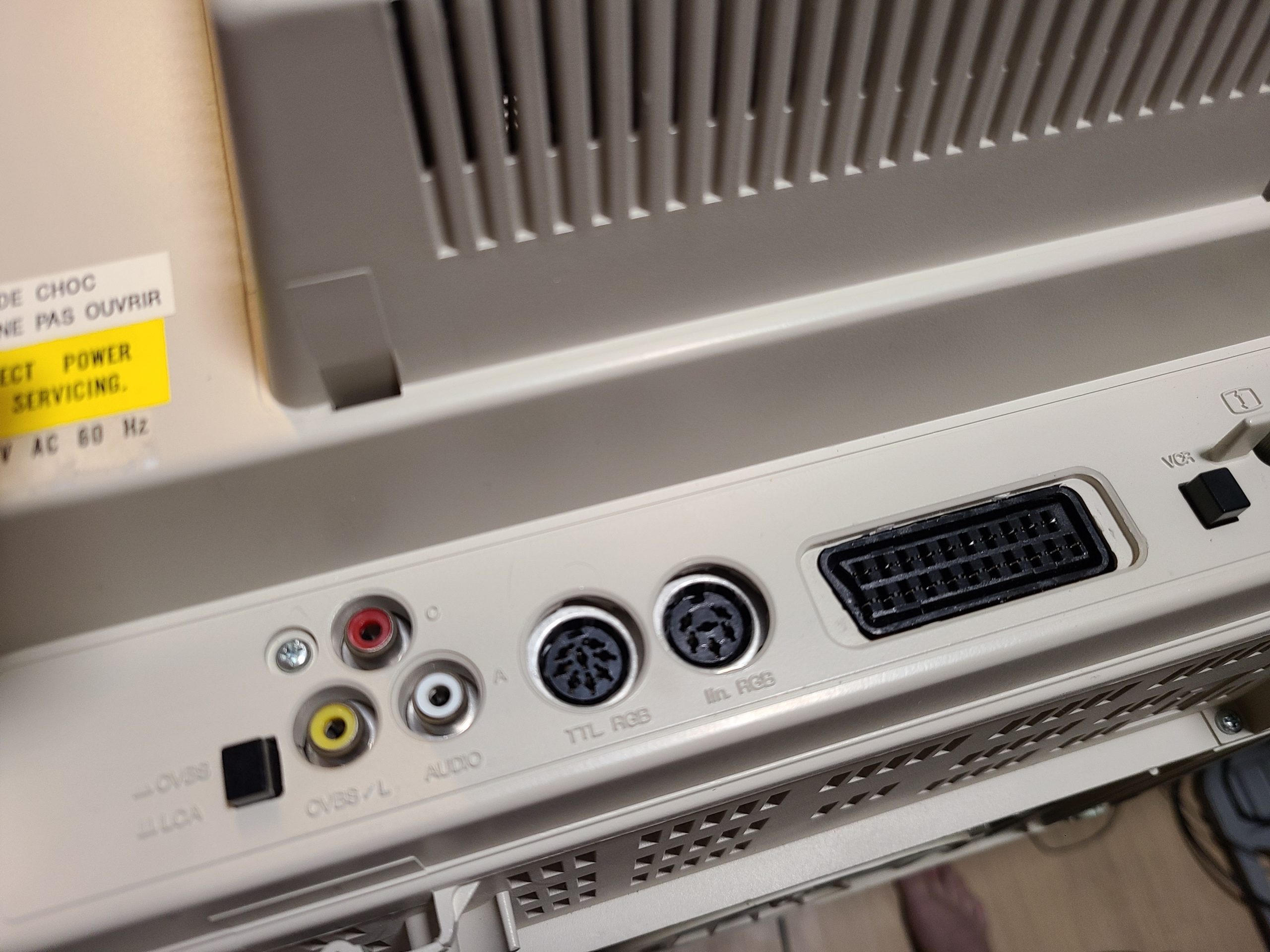
- The North American version has an unused hidden SCART header for RGB input! Just add a connector 🙂
I truly didn’t expect for the process to be as simple as adding a SCART header to the board, but turns out it is! Here is a video showcasing the process from start to finish:
The right-angle SCART header is actually very hard to find as it’s been discontinued in all major parts suppliers. However there is a lot of NOS in Hong Kong that you can get off of eBay. That’s where I found mine – only downside is the 3 week delivery time.
Oh I did not know that the 1084 did not come with scart I have the 1081 and it has it natively.
If you are in the PAL region that would make sense. None of the US market Commodore monitors have SCART afaik. They either use DB9 or DIN6 for RGB input, both of which require adapters to be used with the standard RGB connections we use now.
Hi Andy! great work and thank you for sharing the knowledge. I just got a 1084 monitor -with- SCART connector but -no- DIN6 RGB connector (there is also a DIN8 TTL connector). Can I add the DIN6 RGB connector without any other modifications?
I would assume yes since the reverse is also true 🙂 I haven’t tried it personally yet since nobody has brought me a PAL monitor yet. Same goes for the TTL connector.
thank you andy! I looked at the motherboard and no components seem to be missing. What worried me was the fact that other 1084 models need some components added before soldering a SCART connector to the empty slot. I guess some others are just missing the connector like in our case. Will report back when I get my hands on a connector and solder it in place.
hi Andy! today I installed a din 6 to my 1084 which already had SCART and din8. I see there is image coming in but no sync. The image is scrambled horizontally. Do you have any insight?
I’m confused why you are installing a din6 when your monitor already had two popular options for RGB output?Nevermind I just realized yours has TTL din8 but not analog din6. I’d assume there is something wrong with your sync wiring.FYI I installed missing R404 which brings pin2 into the equation. Din6 has V&H sync and not just composite like the SCART. pins 2&6 go to the sync transistor via R406 & R404 and you need both on the board for Din6 syncing. All good now!