ASUS PG27UQ Power & Fan Issues – A Deep Dive

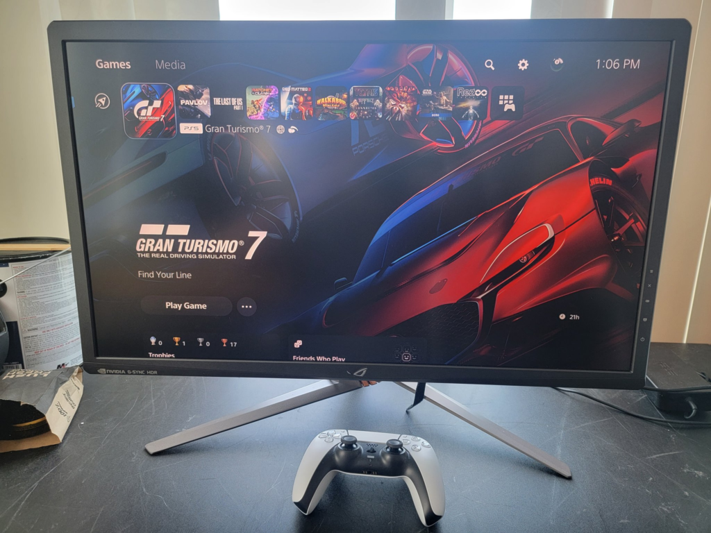
So, if you’re like me, you’re on this page refusing to give up your PG27UQ, because even years later it remains one of the best 4K high refresh rate monitors on the market. Its 98Hz/144Hz 4K refresh, local dimming zones and true 1000 nits peak brightness remains unparalleled… but there’s one problem:

It’s unreliable as fuck.

The heart of the monitor is a short-lived G-Sync module designed and manufactured by none other than NVIDIA themselves.

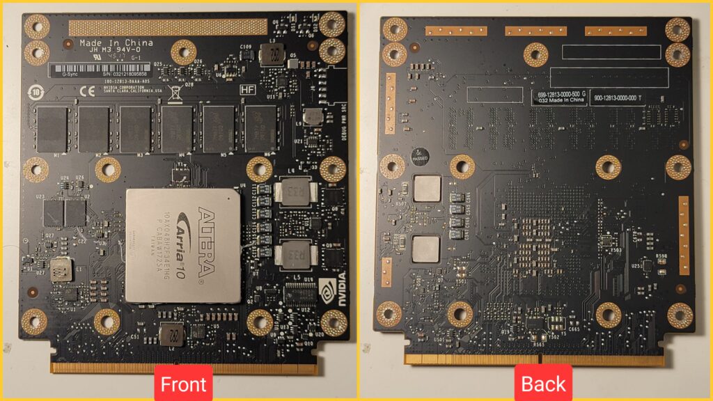
Center-stage on this module is the Altera Arria 10 GX 480 FPGA – a chip with a price tag over $500 at the time NVIDIA was buying them for this module. This chip works very hard (especially in 144Hz mode) to drive the specs that make the PG27UQ so unique. It generates a lot of heat.

ASUS did a decent job at cooling it, despite what you may have read on Reddit. It has two gaming laptop-grade PWM fans – one designated for exhausting air through the FPGA block heatsink down the rear vent in the monitor, and one for exhausting ambient air out the top of the monitor.

Because this FPGA is so powerful, it can’t run for any period of time without a heatsink, and it can’t run for more than maybe 30 minutes without good airflow from the fan.

The G-Sync module has a temperature sensor which monitors the temperature of the FPGA and adjusts the fan speed accordingly.

Now that we’ve gone over the internal design, let’s go over the common problems people run into.

Problem 1: My fans are always running at or near full speed…

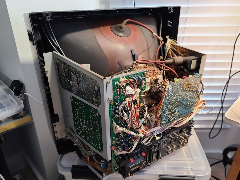
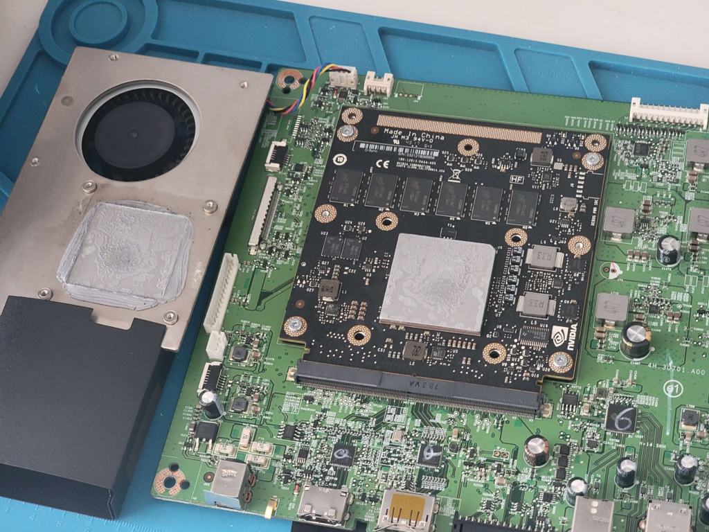
If your fans are running at full speed, it is likely because the FPGA is constantly on the brink of overheating. There could be two reasons for this – the first is maybe your heatsink is full of dust and no longer has proper airflow – or the second most likely reason is the thermal paste on the FPGA has dried up and is no longer transferring enough heat away to the heatsink. You will need to disassemble the monitor, remove the main board, remove the heatsink, clean all dust out of the heatsink fins and the fans, clean all the old paste off with 99% isopropyl alcohol, and apply fresh paste.

Disassembly instructions are out there online – you just remove the rear stand (4 screws), then use a plastic spudger around the seam of the monitor to free the back plastic, then unplug two connectors so you can set the whole piece aside.

To remove the main board, you unplug everything, remove the small screws near the bezel edge at top and bottom, remove the screw holding down the top fan, take the board assembly off the back panel (careful of the plug behind it), flip it over, remove 4 screws, push back the two tabs holding the PCB down, then lift it out.

The heatsink can be moved with the 4 spring-loaded screws below the FPGA. Loosen then as you would a CPU fan, maintain equal force distributions, etc. Make sure you don’t let them fly away. The heatsink will be really stuck on there, use some twisting and wiggling motions to carefully get it off without bending anything.

Problem 2: My PG27UQ no longer turns on, or takes several attempts to turn on…

If your monitor has thermal issues that go unaddressed for too long, it will start to cause heat damage to the FPGA. ASUS appears to have disabled the thermal-throttle shutdown in their firmware despite it being offered by NVIDIA. Similar to the issues which plagued overheating Xbox 360s and PS3s at launch, the ball solder joints under the FPGA will start to crack and deteriorate from excessive heat, and once they fail your PG27UQ will no longer work.

I found this out because I got my personal PG27UQ as free e-waste from someone who had given up trying to get ASUS to RMA repair the thing. I took it home and based off nothing but a hunch I hit the FPGA with a bench hot air station for a few minutes to try and reflow the outer ball joints of the FPGA, and immediately the monitor started working again normally. Unfortunately though, this was only a temporary fix. It lasted about 6 weeks and then I had to repeat the process again, with diminishing returns. After the third or so time, heating it up no longer fixed anything and the G-Sync module appeared to be dead.

I spent a few weeks researching my options and couldn’t find anyone who would properly reball the FPGA. It takes a lot of specialized equipment and an exact ball template that matches the layout of the FPGA pins. Theoretically it could be done, and I’d love to have someone do it to my dead G-Sync module, please reach out if you have any ideas.

My only option was to find a replacement module.

Resurrecting a dead PG27UQ

I googled dozens of different model numbers and other info related to the G-Sync module hoping to find a stash of them somewhere. I even tried AliExpress, eBay, and other marketplaces that sell direct from China. Nothing came up.

I don’t even remember where I found this text, but eventually I tried searching “10AX048H2F34E1HG P CABAW2001A G-Sync Module Card” and got a hit on eBay Canada for a repair shop that had a stockpile of 20 cards…!

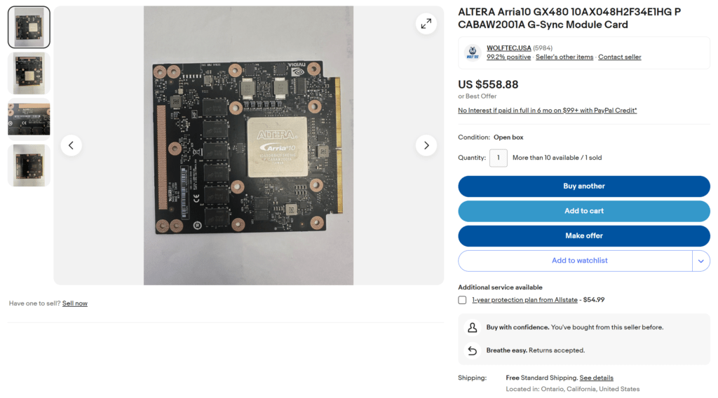
The price tag was pretty painful – in my local market you could get a working PG27UQ for only a couple hundred dollars more. I sent an offer with a quick paragraph explaining my dire little situation and the seller was generous enough to accept a $300 offer from me. I asked them in DMs if they knew where the cards had come from (direct from NVIDIA? Dead stock from China? Pulled from PG27UQs with dead panels?) but they were pretty tight-lipped about it. They probably aren’t supposed to have them 😂

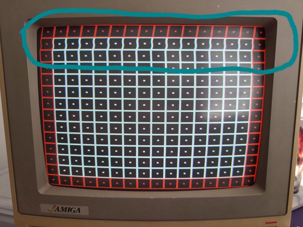
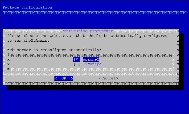
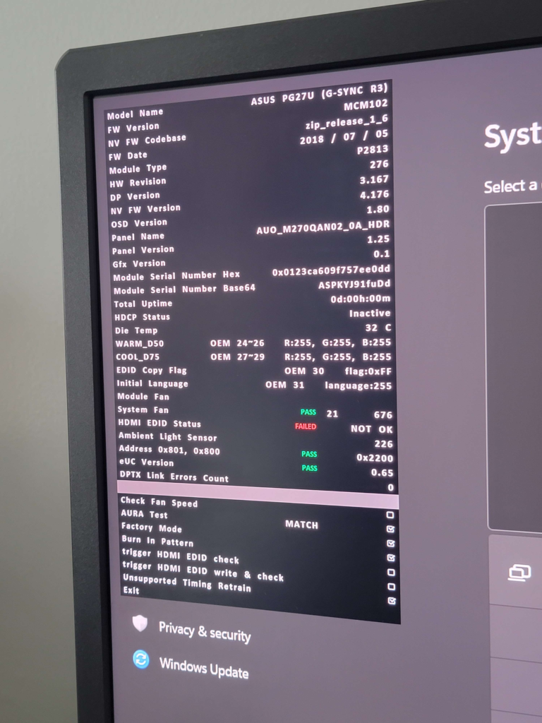
The suspense was killing me, I had no idea if this replacement would work. Would it even boot? Would I need some unobtanium FPGA firmware from ASUS? I installed it and booted the monitor. The screen was flashing red, green, blue, white, repeatedly – looked like some sort of factory burn-in test to make sure the panel was operational. I also saw this curious service menu in the upper corner:

You can see the module is indeed brand new – 0h 0m on the total uptime clock. If you are following along with me, it’s important to first uncheck “Burn In Pattern” BEFORE unchecking “Factory Menu” because I have no clue how to get back into that factory menu once its closed. You don’t want your brand new module to be stuck showing a burn-in pattern forever 🙂

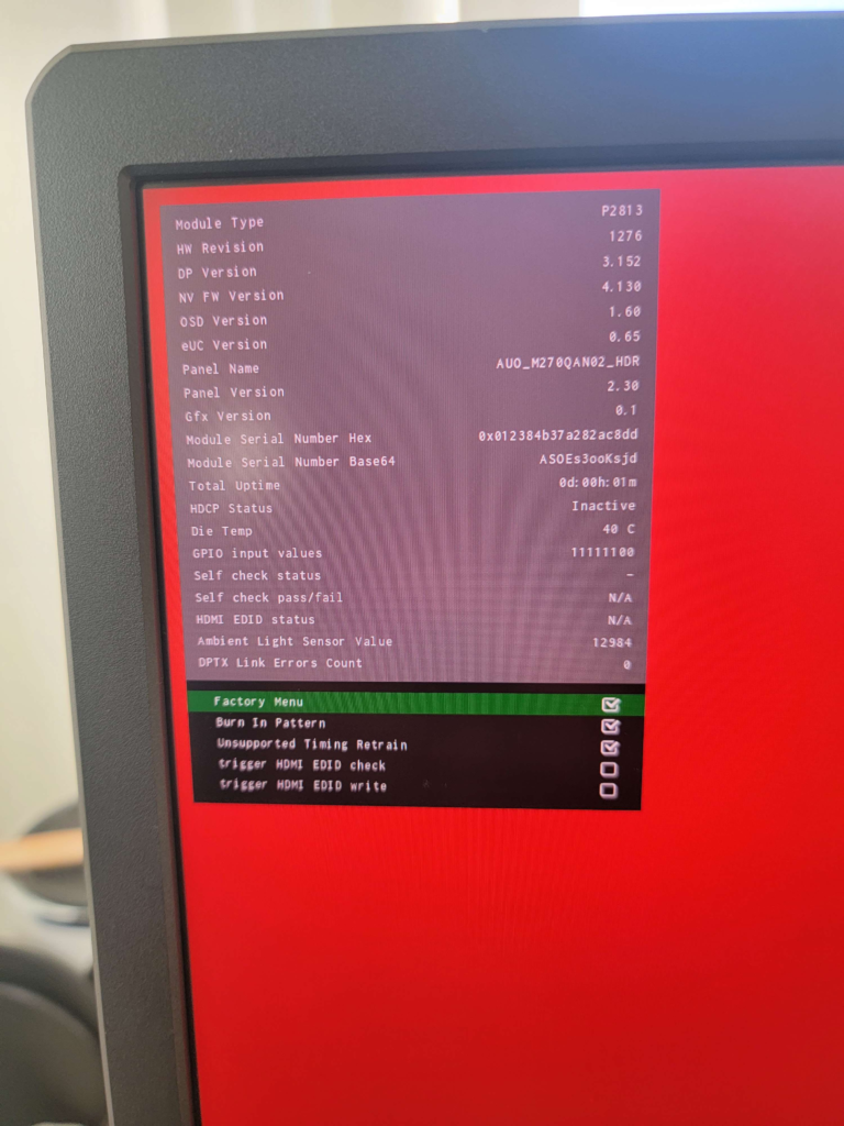
One time with the old dead module after I reflowed the FPGA it showed a factory menu too, which I’ll include here for posterity and comparison:

If you’ll notice, the “NV FW Codebase” changed from “zip_release_1_6” to “4.130” and the “FW Version” changed from MCM102 to [nothing]. This will be a problem…

These NVIDIA modules from eBay came with nothing but OEM firmware on them. Apparently NVIDIA designed the base of the firmware and then ASUS (and possibly Acer?) made their own customizations to it for branding and additional features. Thankfully most of the features we’ll be missing are cosmetic – the ROG projection and ASUS logos won’t work anymore. Instead, you get this cute little NVIDIA menu:

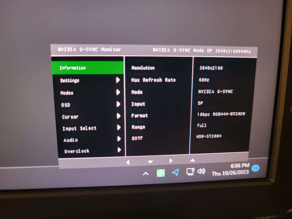
You’ll find all the features you need in this menu including Ref. White Nits, 144Hz OC on/off, user-mode white balance, etc.

Now lets go over the important non-cosmetic broken things, in order of most fucked to least fucked:

  1. The PWM fan system is now inactive
  2. The power button doesn’t actually turn the monitor off – only the backlight.
  3. The power light only works briefly when the monitor is plugged in, then turns off.

I tried various things to flash the ASUS firmware onto the G-Sync module but nothing worked. I even tried contacting ASUS asking for their firmware utility but as of writing they have not provided anything. I do wonder if someone could extract the firmware from a working ASUS-flashed FPGA but I don’t know anything about that. So for now we’re left to work around these issues.

The only way I’ve found to work around the power button issue is to physically unplug the monitor when not in use. You can either used a switched power strip below your desk or do what I do and just unplug power from behind the monitor when I want to turn it off.

Working around the missing PWM Fan System

This solution was inspired from the posts on Reddit of people putting aftermarket PWM controllers into their PG27UQ. This is actually perfect for replacing the now-not-working PWM system from the NVIDIA firmware.

Please use some common sense when installing the fan controller – don’t run the monitor with the heatsink removed. Ever. Also try to avoid working on the monitor internals while its plugged in, just to avoid shorting anything out. Also this entire process can be done with off the shelf plug and play adapters, you don’t need to be soldering anything or altering the monitor in any irreversible way.

First you’ll need this PWM controller: https://www.amazon.com/dp/B08ZDBDSN8

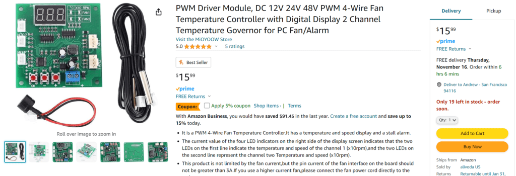
I mounted it with some velcro – if you’re extra paranoid you can cover the back with kapton tape to isolate it from the metal panel backing but I found that unnecessary. Don’t bother plugging in the beeper speaker unless you want to annoy yourself.

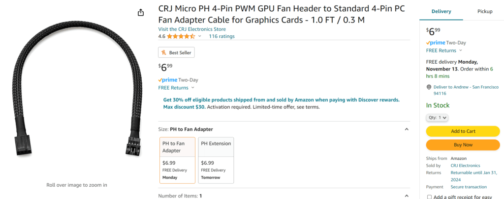
To adapt the 4-pin fan headers on the controller to the micro 4-pin laptop fan connectors in the monitor, I bought two of these adapters off Amazon: https://www.amazon.com/dp/B07S4L41TN

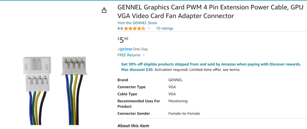
For connecting power to the PWM controller, I bought this extension cable and cut one end off + stripped the yellow and black wire. Yellow is +12v and black is GND, plug it into either of the fan connectors in the PG27UQ board and put stripped end into the screw terminals of the PWM controller: https://www.amazon.com/dp/B07PFK926D

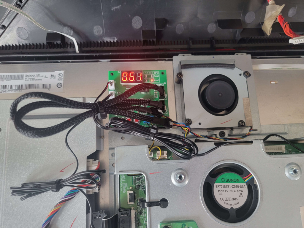
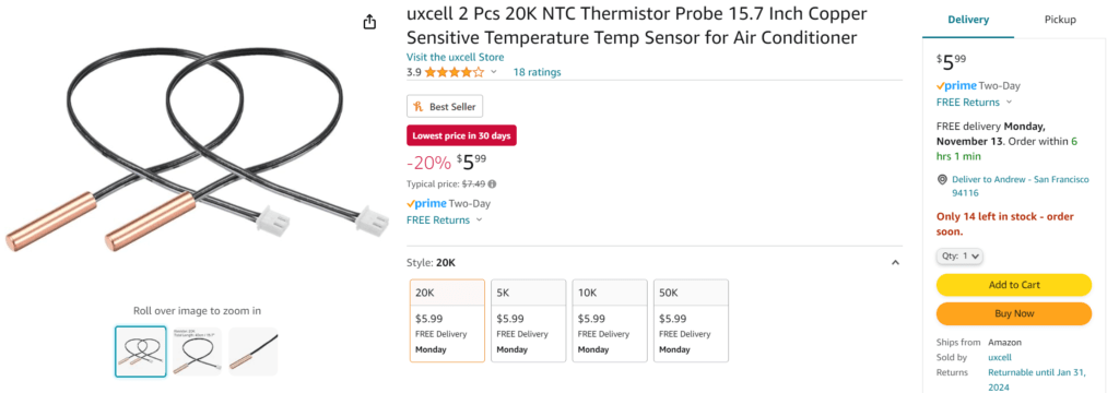
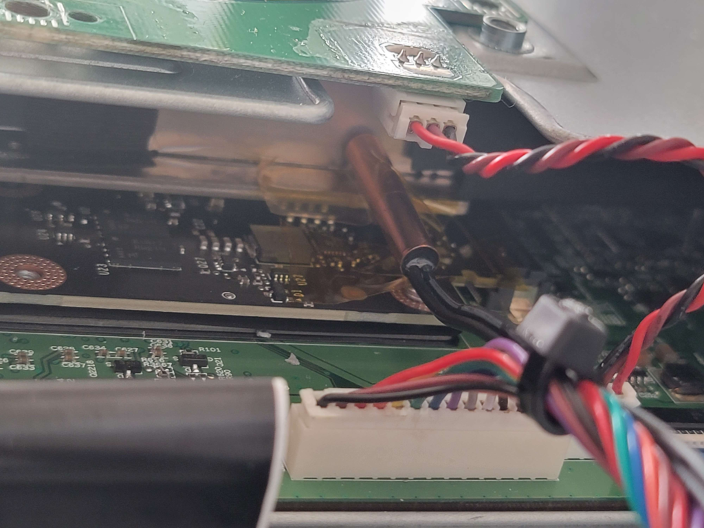
Lastly you need to install some temperature probes. The PWM controller comes with two but they are crap. They fail from heat exposure when attached directly to the heatsink, and are not sensitive enough to work as ambient air sensors inside the monitor. Instead, I suggest buying this 20K copper one: https://www.amazon.com/dp/B07LGL3WJY

You only need one, and you will plug it into the NTC probe connector that corresponds to the Fan # you used for the FPGA fan. You’ll want it to make direct contact with the FPGA heatsink, like this. I used some kapton tape to secure it, plus a zip tie:

You’ll need to adjust the PWM controller base speed for both fans. You do this by pressing “OK” until you see two lights on the fan # you want to adjust, then the arrows to adjust speed (starting at 10, maxing at 50). You will likely want about 30 for the top fan and ~35 for the FPGA fan.

Conclusion

So now other than having to unplug the freakin’ thing when I’m not using it, my PG27UQ is working mostly the same as it should minus some cosmetic ASUS features I won’t miss. Hopefully we get the ASUS firmware flashing tool some day – I’ll update this article if I ever do. Or who knows, maybe PC monitor technology and pricing will finally out-pace this nightmare so I don’t need to hold onto it for dear life anymore. We’ll see what happens first 😂

Commodore 1084 SCART Mod

Most revisions of the Commodore 1084 were produced with the same internal circuitboard for all regions – which for a monitor with factory RGB inputs means two important things:

  1. All regional versions are compatible with both NTSC and PAL signals due to reuse of parts.
  2. The North American version has an unused hidden SCART header for RGB input! Just add a connector 🙂

I truly didn’t expect for the process to be as simple as adding a SCART header to the board, but turns out it is! Here is a video showcasing the process from start to finish:

The right-angle SCART header is actually very hard to find as it’s been discontinued in all major parts suppliers. However there is a lot of NOS in Hong Kong that you can get off of eBay. That’s where I found mine – only downside is the 3 week delivery time.

Sony PVM 5041Q No Composite Fix

This week I fixed a 5041Q which had a broken composite input. You can see a summary of the repairs on my YouTube Channel:

The REMOTE input on the back of the monitor was shorting out the Line/RGB switching circuit, sending 12v at all times regardless of if the switch was toggled on or off for the front of the monitor. Simply removing the port, checking for broken pins, and reseating the REMOTE plug resolved the issue.

NEC DM-2000P CRT Monitor

I recently got my hands on a NEC DM-2000P CRT Monitor that needed geometry and color calibrations. I noticed that there is pretty much zero documentation on this monitor online – I guess none of it got digitized. Last mention of it I saw on the internet was from someone who apparently had a hard-copy of the user manual in 2010…

I am going to document as much information here as I can so that anyone else who has this monitor or is considering buying it (or a similar one: DM-2000A, DM-2600P, DM-3000P) can be more informed.

Specifications

I haven’t even been able to find a spec sheet on this monitor so here is what I’ve been able to determine:

  • Screen Size: 20″
  • TVL: 450?
  • Tube: NEC E814B22
  • Inputs: 34-pin RGB, 1x VTR, 1x S-Video, 2x Composite, 1x external remote
  • Multisync 15-35.5Khz horizontal, 50-87KHz vertical (Source)
  • RGB Capability: Analog & TTL
  • Year of manufacture: 1989 (datestamped inside)

CRT Gallery (assembled)

Publications / Press

I found a blurb in an old scan of PC Magazine (May 14th, 1991, page 374-375) about the 30″ version of this monitor – the DM-3000P. It’s identical to this monitor except for the larger picture tube size. Here is my transcription of the article from the image I found.

NEC is certainly one of the big names in computer monitors, and here is a big monitor bearing the NEC label. Unfortunately, besides the logo, the DM-3000P shows little evidence of the usual NEC quality. The monitor has a 30-inch diagonal screen and a load of features, and its price tag is not small. At $5,600 ($10,734.08 – adjusted for inflation), the DM-3000P isn’t nearly the lowest-priced monitor in this roundup, and it sports moderate features to boot.

With the DM-3000P, you get a unit with specifications comparable to those found in some of the competing models. For example, the 50-87 Hz vertical and the 15 to 35 kHz horizontal scanning frequency ranges are on a par with the others. The DM-3000P’s 0.80 mm dot pitch is large when compared with smaller monitors but still a bit better than average for this class of display.

The unit comes with internal stereo speakers (though these sounded tinny at best), external speaker connections, and stereo signal-out connectors for an amplifier. The unit supports both composite and S-video signals, and it can pass these signals through to other monitors.

While it is possible to connect directly with the monitor, you will want to use the IPS-100 VGA interface that is included with the unit (see below for pictures). This interface is a separate video controller box that modifies a VGA or 8514/A signal to give you better images on-screen. The monitor itself only provides one set of analog controls for basic picture geometry settings, but the IPS-100 interface adds additional controls that allow you to adjust for optimal image size as you move between different display-adapter modes.

In an apparent contradiction, NEC specifications claim the ability to handle the signals up to 1024-by-768 interlaced, but they only claim a monitor resolution of 640-by-480–which means that you can feed the higher resolution signals into the controller, but the monitor won’t be able to resolve a crisp image for anything finer than 640 by 480. In addition, the DM-3000P has a bandwidth of only 20MHz, which is lower than competing designs and limits its ability to produce clear high-resolution images.

Performance results were erratic. The image was sharp and well-converged at the center of the screen, but the beams spread a bit and lines got thicker toward the corners. There were also significant horizontal convergence and pincushioning problems with this model, especially in the lower right corner.

Overall, the DM-3000{ is a less than attractive value. Larger than some of the units in this review, the DM-3000P comes with adequate image quality and a barely sufficient collection of features. If you are looking for a large-size video and VGA display, you could easily find a better buy than the DM-3000P.

— Alfred Poor – contributing editor of PC Magazine.

PC Magazine, May 14th 1991

NEC / Sony 34-pin RGB Info

The 34-pin RGB input is the same pinout as Sony’s standard input, which is well documented online. You can use a floppy drive cable as the connector for the TV-side of your adapter if you choose to make one yourself like I did:

34-pin RGB to Female SCART adapter cable

If you do use a floppy cable, take care to test the pins yourself using a multimeter to understand how the wires translate to the pins on the connector. The pin configuration of floppy cables is typically a side-by-side row pair, whereas the pin configuration of the NEC/Sony connector is two columns.

NEC / Sony 34-pin RGB input pinout

You only need to wire up the following pins shown below. The floppy wire you use will be different from cable to cable so I won’t bother trying to explain that part. Just make sure that whatever wire you use is leading to the correct pin on the TV’s connector or nothing will work. CSYNC is assumed at the source, I have not tested with sync over composite video.

Note that CSYNC is fed to both the H and V sync pins even though the diagram above says H-Sync supports composite sync… I couldn’t get vertical lock on my picture without hooking up to both H and V Sync pins.

NEC Pin #SCART Pin #
Ground6 (or any other ground)4, 5, 9, 13, 18
Red257
Green2611
Blue2715
Sync30, 3120
Audio L246
Audio R202
NEC / Sony 34-pin RGB to SCART pinout

NEC IPS-100 interface

This item was mentioned in the PC Magazine article I mentioned earlier – it appears to be a conversion box to downscale high resolution VGA to 640-by-480 as well as provide compatibility with different common video input connectors. I found a listing on recycledgoods.com for one that was already sold, I downloaded the pictures in case they eventually get lost:

Disassembly

None of the potentiometers inside are labeled except those you can see in the “RGB Drive/Bias” image above. Those are R-Drive, R-Bias, G-Bias, B-Drive, and B-Bias. Nothing else is labeled. Notice there is also no adjustment for G-Drive.

RGB-Pi (OS 3) Screen Deformations & Sync Issues Fix

2023 Update: RGB-Pi OS 4 seems to have resolved all this nonsense once and for all. I suggest just updating to that OS and forgetting about trying to get OS 3 to display correctly if you’re having issues.

RGB-Pi is an excellent pixel-perfect emulation solution which gives proper 240p output via SCART to RGB-compatible CRT monitors.

Although compatibility is high out-of-the-box, many CRT monitors (especially professional/non-consumer models) will not accept the csync signal that RGB-Pi outputs. There are two different issues that can happen but both involve the same problem – you may have issues with only the RGB-Pi menus, only with emulation, or with both.

If your screen looks like any of the following pictures, this guide will most likely will fix your problem:

Sync deformation in 240p emulation (SNES 240p Test Suite ROM). Monitor: Amiga 1080
Sync deformation in RGB-Pi OS. Monitor: Sony PVM-1943MD

The RGB-Pi OS has two different “configurations” for displaying 240p content. The first displays the user interface (the menu of RGB-Pi where you select your game or change settings) and the second config is for displaying 240p emulation. Sometimes only one of these configs will have sync issues on your TV, sometimes both of them will.

OS/UI Sync Issues

If you have sync issues with the main menu of RGB-Pi OS, you need to read this section, otherwise skip it.

To fix sync issues happening on the main menu of RGB Pi (see 2nd image above), you will want to edit a file called config.txt. This can be accessed any of the following ways:

  1. Plugging in your RGB-Pi micro-sd card into a Windows or Linux-based computer
  2. Connecting to your Pi via SSH
  3. Connecting to your Pi via SCP/SFTP

In method #1, you will find it at the root of the sd card. In methods #2 and #3, you will need to browse to the /boot directory to find it.

Once you open the file with a text editor, you will see this on the first line:

hdmi_timings=320 1 10 30 40 240 1 3 4 6 0 0 0 60 0 6400000 1

These are the settings used to generate the video signal of the RGB-Pi OS. If you are wondering what these numbers all represent, here is a handy chart in order of each setting’s appearance for hdmi_timings:

h_active_pixelsh_sync_polarityh_front_porchh_sync_pulseh_back_porchv_active_linesv_sync_polarityv_front_porchv_sync_pulsev_back_porchv_sync_offset_av_sync_offset_bpixel_repframe_rateinterlacedpixel_freqaspect_ratio
3201103040240134600060064000001
hdmi_timings chart

The only two numbers we care about here are h_sync_pulse (4th number in the list) and v_sync_pulse (9th number in the list). These are the numbers that control most of the sync deformations you encounter. Now that you know where to find these numbers, continue reading Adjusting the Sync Pulse below to learn how to adjust these numbers and fix your menu sync.

240p emu sync issues

If you have issues with sync during game emulation, you need to read this section, otherwise skip it.

Each console RGB-Pi is capable of emulating has its own configuration settings to produce the correct pixel-perfect 240p picture on a CRT monitor. Usually all that needs to be adjusted to fix a sync deformation is the V-Sync or H-Sync pulse value. These values can be found in the following file:

NOTE: This file is only accessible via SSH/SFTP!! You won’t find this file on the SD Card!

/home/RGB-Pi/data/timings/console-timings.txt

In this file you will see a line for every console, both 60Hz and 50Hz seperately. They are separated because 50Hz requires a different amount of horizontal lines to be displayed. You may have already discovered before reading this guide that playing your games at 50Hz fixes the sync issues – however that is not a desirable solution for most people. The actual solution will be to change the sync pulse lines for every console in this file. Fortunately they all use the same default values, so you don’t have to manually test each console for different numbers. Pick one console you can test a ROM with (I picked snes60 for 60Hz SNES emulation).

consoleH PixelsScanlinesFrame RateH PosH ZoomV PosH Front PorchH Sync PulseH Back PorchV Sync PulseH Frequency
snes60192024060.0000048192240515734
SNES 60Hz default timings

If you need to understand how to adjust the pulse numbers, read the section Adjusting the Sync Pulse below before continuing.

Once you find the right pulse numbers on your test console, copy it to every other console in the file. You can do this with a simple Find/Replace function in the text editor. For V-Sync pulse be careful not to just replace “5” because there are other numbers that contain 5’s like the pixel clocks. Try searching “240 5” and replacing with “240 x” where x is your sync number. This will only touch the v-sync pulse.

Adjusting the Sync Pulse

Once you know where to adjust the pulse numbers, start by adjusting V-Sync Pulse first. Lower the number down from the default of 5 (for 240p) or 4 (for RGB-Pi OS) by increments of 1. Test after each time. In order to test, you must REBOOT the RGB-Pi OS using the START menu REBOOT option. Do not simply unplug the Pi, this may reset your changes. If you are testing the OS for sync issues, just wait for it to finish booting and see if your sync issues are gone. If you are testing for emulation sync issues, boot into the console you edited in console-timings.txt and see if the issues are gone.

If vertical sync adjustment doesn’t solve your issue, try adjusting the h-sync value in increments of 5-20 using the same process.

If you get rolling sync from decreasing the values, try increasing them instead.

Amiga 1080 running RGB 240p Sega Genesis Emulation with perfect sync 🙂

osTicket Gmail IMAP Fixes

In the ever-ongoing list of osTicket bugs and quirks, there are a few IMAP/Gmail-related ones I continuously run into. If you are having issues connecting osTicket to a Gmail account for sending/receiving emails over IMAP and SMTP, ensure you have done all of the following steps:

  1. Log into the Gmail account from a browser to make sure you have the correct credentials. While you’re logged in, make sure IMAP is enabled from the Settings.
  2. In osTicket, you will have to jump through a number of hoops to get it to correctly re-try an IMAP connection that was previously working:
  3. Go to Admin Panel -> Email
  4. Disable SMTP entirely at the bottom by checking the radio box. You will enable it again later when IMAP is working.
  5. Change the Mail Fetch setting from IMAP to POP (yes, I know this sounds counter-productive but bear with me)
  6. Change the port from 993 to 995
  7. Erase “INBOX” from the Folder name box
  8. Enter the user and password for the GMail account.
  9. Try to Save Changes at the bottom.

osTicket should be able to log in correctly via POP, which will then clear out whatever issue is causing it to fail with the IMAP connection. Now you can change the settings back to IMAP and watch as osTicket magically succeeds in connecting despite previously failing with the exact same settings:

  1. Change the setting back to IMAP
  2. Enter INBOX for the folder name
  3. Change the port back to 993
  4. Re-enter your Gmail credentials just to be thourough.
  5. Try to Save Changes at the bottom
  6. Re-enable SMTP and Save Changes again.

WordPress WP_Media_Image Widget Link Rel

WP_Media_Image widgets support a lot of options, but almost none of them are exposed to the end user. For example, there are toggles for adding target=_blank to the link of a WP Media Image Widget.

Adding this filter to your functions.php will force all WP_Media_Image widgets to link externally without any intervetion from the blog administrators:

function add_blank_target_to_image_widget( $instance, $args, $widget ) {
	$instance['link_target_blank'] = true;
	return $instance;
}
add_filter( 'widget_media_image_instance', 'add_blank_target_to_image_widget', 10, 3 );

osTicket broken after an update from 1.10.x? This is probably the fix for you.

I recently tried to update my osTicket installation only to find it broken after upgrade with messed up menus and missing ticket queues.

If you’re still using a version of osTicket from 2018 or earlier, you are probably still on 1.10.x or lower. It’s definitely time to upgrade but before you do, there are some important steps you’ll want to follow to ensure a successful upgrade. Keep in mind if you are on osTicket 1.6.x or older, you can’t use the upgrade system at all according to the osTicket documentation for upgrading. You’ll have to migrate the date manually, which is not covered in this article.

So if you’re like me and your osTicket installation is broken after upgrading, take a look at these symptom lists below. If you haven’t tried upgrading yet, skip down to the last resolution below.

Symptom

  • All dropdown menus are broken/have css issues
  • All ticket queues are missing

Resolution

Make sure you are using PHP 7.1+. PHP 5.4 support was never officially dropped from the osTicket system requirements but it clearly causes problems past v1.10.x. Obviously at the time of writing PHP 5.x is EOL as of December 2018 already and should be phased out, but just last year osTicket still required PHP 5.x. So that’s a shame but let’s move past it.

Symptom

  • I managed to get osTicket upgraded to 1.14+ but I still see DB Error #1064 show up occasionally in the logs

Resolution

One or more of your users may be using a saved ticket search left over from an old version of osTicket which is no longer compatible. Deleting and recreating the saved search will resolve the error. See this reply on GitHub.

Symptom

  • I upgraded osTicket and now email fetching isn’t working (ticket responses/requests are not getting processed even when the cron is run manually)

Resolution

After an upgrade, sometimes osTicket needs you to re-enter the password for the account (yes, even if SMTP is still working). Re-enter the password on the email settings page (Admin Panel -> Emails -> (your desk email) -> Password)

Symptom

  • I’m getting database error logs/emails
  • I can’t make any changes to settings or tickets
  • I can’t create new tickets

Resolution

First off, just like the first symptom/resolution in this article, you should make sure you’re on PHP 7.1+ If you’re like me, you already checked that and everything is still broken. So in that case, I hope you have a database backup of your original installation pre-upgrade because it’s time to go back.

Step 1.

Rollback your osTicket database to how it was before everything broke.

Step 2.

Delete osTicket from your server and download the release you were on before everything broke: https://github.com/osTicket/osTicket/releases

Step 3.

After you have osTicket working again, we’re going to approach upgrading in a more incremental manner. osTicket keeps track of all the schema updates between your version and the upgrade, but as with all open source projects sometimes someone makes a minor change that causes retroactive problems for people like us who are behind the times. I’ll assume that you started on osTicket 1.10.x (specifically I was on 1.10.4) but this should apply to other relevant versions as well ( see first paragraph of this article, terms apply).

Download the next major version release, which in my case is 1.11. Upload the files to your server and initiate the upgrade process. Let the upgrade finish, and PHP 5.x users watch as your ticket queue disappears. Switch to PHP 7.1+ to fix this. During this entire process you will probably continue to see DB Error #1064 get logged but rest assured it will be gone by the time you’re done upgrading.

Step 4.

Continuing with our incremental upgrade approach, download the next major version release, which for me will be 1.12. Let it upgrade, and osTicket should still be working fine. Woohoo!

Step 5.

Curiously there is no 1.13 release on GitHub, so we will go with the next best thing: 1.12.5. Same rules apply, upgrade it and watch as nothing breaks. Since there were no schema upgrades, the upgrade will be instantaneous with no prompt to upgrade in osTicket. Version should report as 1.12.5 in Admin Panel. You could probably skip 1.12 and go straight to 1.12.5 if you want, but I’m not 100% sure.

Step 6.

We’re getting closer to 1.14.x. Are your palms sweating yet? Go ahead and install it. While you wait, pat yourself on the back.

Conclusion

You may be wondering why this worked. Unfortunately I don’t have an answer for you. If I had to guess, running the upgrades one by one with PHP 7.1 switched on after leaving 1.10.x may have been the reason it was successful.

Congratulations, your osTicket installation is no longer broken from an upgrade, and the menus and ticket queues are no longer messed up or missing.

I have no idea if all the aforementioned incremental steps were necessary or if this same process could have been done with fewer upgrade steps. However, I know this particular upgrade path worked for me and I don’t want to waste my time going though every single potential upgrade path to find the shortest one. I want to get on with my life, as I’m sure you do. Go back to closing tickets. Don’t forget to delete the setup folder from osTicket’s installation directory and also check out my other articles.

Fix phpMyAdmin displaying PHP code or showing ‘File not found’ on Apache 2.4+ with php-fpm

If you enabled php-fpm after previously using mod_php for Apache, you’ll notice that your phpMyAdmin URL will no longer work. Raw PHP code will be displayed instead of rendering a page. Don’t worry, this hasn’t exposed your db password or any other compromising details.

Fixing the PHP code output

Apache is rendering the raw PHP code because you initially configured it to use mod_php and have disabled that module in favor of php-fpm. phpMyAdmin doesn’t reside within the usual /var/www/html/ directory which uses php-fpm. Therefore you have to add a ProxyPassMatch directive to your Apache site conf to tell it to route any file ending in .php through php-fpm’s socket. Add the following to your site’s conf (default is /etc/apache2/sites-enabled/000-default.conf):

ProxyPassMatch ^/(.*\.php(/.*)?)$ unix:/var/run/php/php7.2-fpm.sock|fcgi://./var/www/html

Next, reload the Apache service:

sudo service apache2 reload

Now if you try to access phpMyAdmin you’ll likely still run into a problem: File not found.

Fixing ‘File not found’

phpMyAdmin is trying to load from /var/www/html/ yet all of its files are stored in /usr/share/phpmyadmin/. You can quickly fix this by adding a symlink from the phpmyadmin directory to the Apache document root:

sudo ln -s /usr/share/phpmyadmin /var/www/html/

Now if you try once more to access phpMyAdmin it should work. If you still encounter File not found you may need to double check that /etc/apache2/conf-enabled/phpmyadmin.conf exists. If it does not, you can add it using another symlink:

sudo ln -s /etc/phpmyadmin/apache.conf /etc/apache2/conf-available/phpmyadmin.conf
a2enconf phpmyadmin
sudo service apache2 reload

Finally if you try again. phpMyAdmin should be working at this point. If you still can’t get into phpMyAdmin, you can try running a re-configuration:

Re-configuring phpMyAdmin

IMPORTANT: Do not allow the reconfiguration to reinstall the phpMyAdmin database in the following steps!

Reconfiguring phpMyAdmin can be helpful if you believe there is something wrong with your Apache configuration for phpMyAdmin. There is a tool which can attempt to correct basic configuration issues with phpMyAdmin. To reconfigure phpMyAdmin:

sudo dpkg-reconfigure -plow phpmyadmin

On the screen that comes up, hit enter to advance to the first step of re-configuration. It will ask you if you want to reinstall the database for phpMyAdmin. Highlight NO and hit Enter. If you reinstall your database you will lose all personal configuration options and may break your phpMyAdmin installation even further.

After selecting No, you will be shown this screen:

phpMyAdmin reconfiguration (step 2)

You should see an astrisk (*) next to apache2 by default, but if not you must select it by pressing your spacebar. Afterwards hit Enter to continue with the apache2 configuration step. You should see output similar to the following to confirm the configuration completed without any issues:

dbconfig-common: writing config to /etc/dbconfig-common/phpmyadmin.conf
Replacing config file /etc/dbconfig-common/phpmyadmin.conf with new version
Replacing config file /etc/phpmyadmin/config-db.php with new version
dbconfig-common: flushing administrative password
apache2_invoke phpmyadmin: already enabled

You should now be able to use phpMyAdmin again!